 |
Langley Research CenterTurbulence Modeling Resource |
Jump to: SA Results, SA-RC Results, SSTm Results, SST-2003m Results, SST-RCm Results, BSLm Results, Wilcox2006-klim-m Results, K-kL-MEAH2015m Results
Return to: Axisymmetric Transonic Bump Validation Intro Page
Return to: Turbulence Modeling Resource Home Page
Axisymmetric Transonic Bump Validation Case
SSG/LRR-RSM-w2012 Model Results
Link to SSG/LRR-RSM-w2012 equations
Note that thorough
grid studies were not performed for validation cases such as this one.
Some effort was made to ensure reasonable grid resolutions, but there may still be
small noticeable discretization errors. Therefore, these validation results shown should be considered
representative, but not "truth."
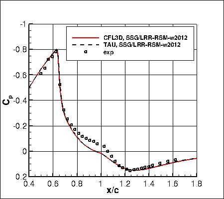
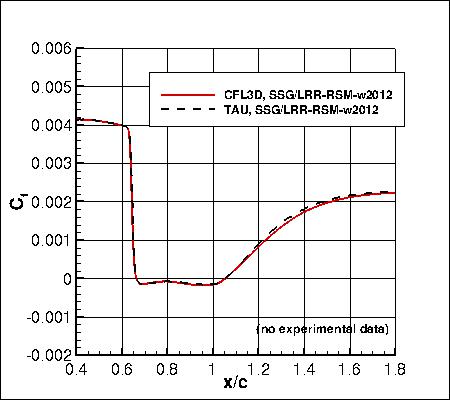
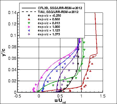
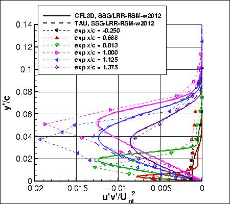
The plots compare the SSG/LRR-RSM-w2012 results from
two independent CFD codes, CFL3D and TAU, with experimental data.
The CFD codes predict the flow separation to occur at approximately x/c = 0.66 and reattachment at x/c = 1.05
(in experiment these were 0.7 and 1.1, respectively).
CFL3D code used freestream turbulence intensity=0.0089% and freestream turbulent viscosity (relative to laminar)=0.009
(additional details can be found in the CFL3D User's Manual, Appendix H),
while TAU used freestream turbulence intensity=0.1% and freestream turbulent viscosity (relative to laminar)=0.1.
Please read note 5 on Notes on running CFD page.
The TAU results are from the second-finest grid (721x321), while the CFL3D results are from the finest grid (1441x641).
Both codes yielded similar results for all quantities.
The data files from CFL3D are given here:
axibump_cfl3d_cp_ssglrrrsm.dat,
axibump_cfl3d_cf_ssglrrrsm.dat,
axibump_cfl3d_u_ssglrrrsm.dat,
axibump_cfl3d_uv_ssglrrrsm.dat.
(Note: the profiles have been interpolated using Tecplot software onto pre-set points, that may or may
not correspond to the actual grid points or grid cells used in the computation.)
A typical CFL3D input file is:
axibump_cfl3d_typical_ssglrrrsm.inp.
A typical FUN3D input file is:
fun3d.nml_typical_ssglrr_2.
In this case CFL3D
was run on a version of the 3-D grid that was centered around the x-z plane, rather
than on the posted grid that has one plane aligned with the x-z
plane (1 deg. still separated the two planes).
Note that in the CFL3D results for this case, the residuals hung up and did not converge well.
The resulting forces included a very small variation ("buzzing"), but were nonetheless
nonvarying in the mean.
Jump to: SA Results,
SA-RC Results,
SSTm Results,
SST-2003m Results,
SST-RCm Results,
BSLm Results,
Wilcox2006-klim-m Results,
K-kL-MEAH2015m Results Return to: Axisymmetric Transonic Bump Validation Intro Page Return to: Turbulence Modeling Resource Home Page
Recent significant updates: Responsible NASA Official:
Ethan Vogel


01/28/2019 - mentioned that CFL3D version of grid is centered about x-z plane and run here on finest level; updated CFL3D results
12/03/2018 - added mention of nonconvergence of CFL3D results
06/22/2017 - updated plots and CFL3D data to reflect correct Re (previous CFL3D results were at slightly incorrect Re)
01/13/2016 - added link to SA-RC results
02/19/2015 - added Cf, plus minor update to all CFL3D data files
02/11/2015 - added TAU results
Page Curator:
Clark Pederson
Last Updated: 03/06/2025